COMBINED FOOTING DESIGN | DESIGN OF COMBINED FOOTING|Combined footing design as per IS code 456 | Design of Combined Footing excel
Combined footing design as per IS code 456 | Design of Combined Footing excel
COMBINED FOOTING DESIGN IS 456
DESIGN INPUT
Footing Size Design
- Load 1 (Pu1)
- Load 2 (Pu2)
- Combine load Pcu
- Design Load Pc
- Moment in x dir Mux
- Moment in y dir Muy
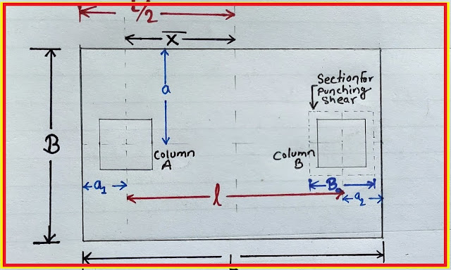
- c/c dist b/w col in x dir
- c/c dist b/w col in y dir
- Col Dim x dir
SBC
Footing Size required A req
Footing Size Provided L B
Area Provided A p
 |
| COMBINED FOOTING DESIGN |
We have uploaded the combined footing design in excel sheet for your reference purpose. this is purely for educational purposes. if some of you have found any doubt kindly comment below so that we will clear your doubts
why we use a combined footings design?
1. If two footings (isolated footing) overlapped.
2. subsoil condition is poor
3. To balance eccentric isolated footing
 |
| combined footing excel download |
Design members for combined footing design
1. slab design
2. shear check
COMBINED FOOTING DESIGN AS PER EUROCODE
1. DESIGN INPUT
- Footing has two columns
- 300mm square column has 100kN and 500kN live and dead loads respectively
- 400mm square column has 200kN and 800kN live and dead loads respectively
- Spacing of columns 3m
- fck = 30N/mm2
- fyk = 500N/mm2
- Assumed footing thickness 500mm
- Allowable bearing pressure 200N/mm2
- Assume effective depth 440mm for initial calculations
2. Calculation of required footing area
Net bearing pressure = 200-25X.500
= 187.5N/mm2
Service load = 100 + 500 + 200 + 800
= 1600kN
Required footing area = 1600/187.5
= 8.53m2
Select footing dimensions as 4.3m X 2m
3. Calculation of center of gravity
Take moment about center of 300mm square column
x = (200+800)X3/(100+500+200+800)
= 1.875m
4. Calculation of Bearing Pressure
Design Load = (1.35X800+1.5*200) + 1.35x500+1.5x100)
= 2205kN
Pressure = 2205/(4.3*2)
= 257N/mm2
5. Check for Punching Shear
Max. Shear Resistance = 0.5ud[0.6(1-fck/250)](fck/1.5)
At 300mm column face
= 0.5*300*4*440*0.6*(1-30/250)*(30/1.5)
= 2788kN > (1.35*500+1.5*100 = 825kN)
At 400mm column face
= 0.5*400*4*440*0.6*(1-30/250)*(30/1.5)
= 3717kN > (1.35*800+1.5*200 = 1380kN)
Hence, Punching Shear is safe
Maximum bending was calculated
It was 209kNm, and it occurred at1.05m from 300mm square column
6. Design for Bending
Longitudinal reinforcements
MEd = 209kNm
K = M/[b*(d^2)*fck]
K = 209*E6/[1000*(440^2)*30]
K = 0.04
Kbal = 0.167 (balance condition is taken based on x = 0.45d)
Therefore
K<Kbal
Compression reinforcement is not required
z = d[0.5+(0.25-K/1.134)^0.5]
z = 440[0.5+(0.25-0.04/1.134)^0.5]
z = 424mm (Z/d = 0.96>0.95)
Therefore
Z = 0.95*440
= 418mm
As = M/(0.87*fyk*z)
As = 209*E6/(0.87*500*418)
= 1150mm2
As min. = 0.15*b*d/100
= 0.15*1000*440/100
= 660mm2
Therefore,
Proved #16@150mm spacing
7. Transverse reinforcements
Bending Moment = 257*(1^2)/2
MEd = 128.5kNm
K = M/[b*(d^2)*fck]
K = 128.5*E6/[1000*(440^2)*30]
K = 0.022
Kbal = 0.167 (balance condition is taken based on x = 0.45d)
Therefore
K<Kbal
Compression reinforcement is not required
z = d[0.5+(0.25-K/1.134)^0.5]
z = 440[0.5+(0.25-0.022/1.134)^0.5]
z = 431mm (Z/d = 0.97>0.95)
Therefore
Z = 0.95*431
= 409.5mm
As = M/(0.87*fyk*z)
As = 128.5*E6/(0.87*500*409.5)
= 722mm2
As min. = 0.15*b*d/100
= 0.15*1000*440/100
= 660mm2
Provide #12@150mm spacing


COMMENTS